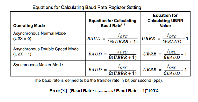
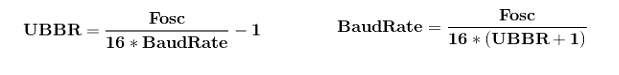
UART INTERFACING WITH AVR
UART stands for Universal Asynchronous Receiver/Transmitter. From the name itself, it is clear that it is asynchronous i.e. the data bits are not synchronized with the clock pulses. In this project we will discuss about UART interfacing with AVR.
Synopsis

UART stands for Universal Asynchronous Receiver/Transmitter. From the name itself, it is clear that it is asynchronous i.e. the data bits are not synchronized with the clock pulses.

USART stands for Universal Synchronous Asynchronous Receiver/Transmitter. This is of the synchronous type, i.e. the data bits are synchronized with the clock pulses.

If you refer to the USART section in the datasheet of any AVR microcontroller, you will find several features listed there. Some of the main features of the AVR USART are:

Full Duplex Operation (Independent Serial Receive and Transmit Registers)

Asynchronous or Synchronous Operation

Master or Slave Clocked Synchronous Operation

High Resolution Baud Rate Generator

Supports Serial Frames with 5, 6, 7, 8, or 9 Data bits and 1 or 2 Stop Bits

Speed (Baud rate)

As we know the bit rate is “Number of bits per seconds (bps)”, also known as Baud rate in Binary system. Normally this defines how fast the serial line is. There are some standard baud rates defined e.g. 1200, 2400, 4800, 19200, 115200 bps etc. Normally 9600 bps is used where speed is not a critical issue.

Description

UART stands for Universal Asynchronous Receiver/Transmitter.

USART Pin Configuration

RxD: USART Receiver Pin (ATMega8 Pin 2; ATMega16/32 Pin 14)

TxD: USART Transmit Pin (ATMega8 Pin 3; ATMega16/32 Pin 15)

XCK: USART Clock Pin (ATMega8 Pin 6; ATMega16/32 Pin 1)

AVR basic Registers

There are mainly three types..

UDR: USART Data Register
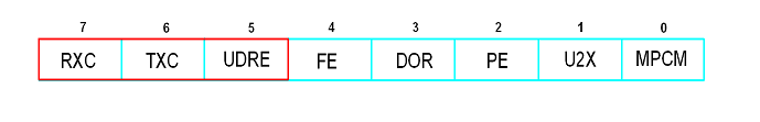
It has basically two registers, one is Tx. Byte and other is Rx Byte. Both shares the same UDR register. Do remember that, when we write to the UDR reg. Tx buffer will get written and when we read from this register, Rx Buffer will get read. Buffer uses FIFO shift register to transmit the data.

UCSRA

USART Control and Status Register A. As the name suggests, is used for control and status flags. In a similar fashion, there are two more USART control and status registers, namely UCSRB and UCSRC.

UBRR

USART Baud Rate Register, this is 16-bit register used for setting baud rate.

UCSRA: USART Control and Status Register A


Bit 7 – RXC: USART Receive Complete

This flag bit is set when there is unread data in UDR. The RXC Flag can be used to generate a Receive Complete interrupt.

Bit 6 – TXC: USART Transmit Complete

This flag bit is set when the entire frame from Tx Buffer is shifted out and there is no new data currently present in the transmit buffer (UDR). The TXC Flag bit is automatically cleared when a transmit complete interrupt is executed, or it can be cleared by writing a one to its bit location. The TXC Flag can generate a Transmit Complete interrupt.

Bit 5 – UDRE: USART Data Register

If UDRE is one, the buffer is empty which indicates the transmit buffer (UDR) is ready to receive new data. The UDRE Flag can generate a Data Register empty Interrupt. UDRE is set after a reset to indicate that the transmitter is ready.

Bit 4 – FE: Frame Error

Bit 3 – DOR: Data OverRun

This bit is set if a Data OverRun condition is detected. A Data OverRun occurs when the receive buffer is full (two characters) and a new character is waiting in the receive Shift Register.

 Bit 2 – PE: Parity Error

 Bit 1 – U2X: Double the USART Transmission Speed

 Bit 0 – MPCM: Multi-processor Communication Mode

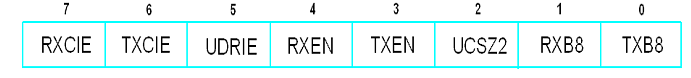
UCSRB: USART Control and Status Register B


Bit 7 – RXCIE: RX Complete Interrupt Enable

Writing one to this bit enables interrupt on the RXC Flag.

Bit 6 – TXCIE: TX Complete Interrupt Enable

Writing one to this bit enables interrupt on the TXC Flag.

Bit 5 – UDRIE: USART Data Register Empty Interrupt Enable

Writing one to this bit enables interrupt on the UDRE Flag.

Bit 4 – RXEN: Receiver Enable

Writing one to this bit enables the USART Receiver.

Bit 3 – TXEN: Transmitter Enable

Writing one to this bit enables the USART Transmitter.

Bit 2 – UCSZ2: Character Size

The UCSZ2 bits combined with the UCSZ1:0 bit in UCSRC sets the number of data bits (Character Size) in a frame the receiver and transmitter use.

Bit 1 – RXB8: Receive Data Bit 8

Bit 0 – TXB8: Transmit Data Bit 8

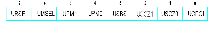
UCSRC: USART Control and Status Register C


Bit 7 – URSEL: Register Select

This bit selects between accessing the UCSRC or the UBRRH Register, as both register shares same     address. The URSEL must be one when writing the UCSRC or else data will be written in UBRRH register.

Bit 6 – UMSEL: USART Mode Select

This bit selects between Asynchronous and Synchronous mode of operation.

0 = Asynchronous Operation

1 = Synchronous Operation

Bit 5:4 – UPM1:0: Parity Mode

These bits enable and set type of parity generation and check. If parity a mismatch is detected, the PE Flag in UCSRA will be set.

Bit 3 – USBS: Stop Bit Select

This bit selects the number of Stop Bits to be inserted by the Transmitter. The Receiver ignores this setting.

0 = 1-bit

1 = 2-bit

Bit 0 – UCPOL: Clock Polarity

This bit is used for Synchronous mode only. Write this bit to zero when Asynchronous mode is used.

 UBRRL and UBRRH: USART Baud Rate Registers


Bit 15 – URSEL: Register Select

This bit selects between accessing the UCSRC or the UBRRH Register, as both register shares same address. The URSEL must be one when writing the UCSRC or else data will be written in UBRRH register.


Bit 11:0 – UBRR11:0: USART Baud Rate Register.

Used to define baud rate


Example: suppose Fosc=8 MHz and required baud rate= 9600 bps.

Then value of UBRR= 51.088 i.e. 51.

Proteus design for UART interfacing with AVR


Orcad design for UART interfacing with AVR


UART Interfacing with AVR

/*  Name     : UARTmain.c
 *  Purpose  : Source code for UART interface with ATMEGA16.
 *  Author   : Gemicates
 *  Date     : 2017-09-09
 *  Website  : www.gemicates.org
 *  Revision : None
 */


#ifndef F_CPU
#define F_CPU 8000000UL              // 8 MHz clock speed
#endif

#include<avr/io.h>   
volatile char Rec_Data;             
 

int main()
{                  
 DDRD  = 0X02;                      // PORTD 2nd pin Is set as Output (RD1=1)         
 UCSRA = 0X00;                      // Clears TXC & RXC Flag Bit                      
 UCSRB = 0X18;                      // Transmission Enabling (TXEN=1)                                                                         
 UCSRC = 0X86;                      // URSEL=1,UMSEL=0,UCSZ1=1,UCSZ0=0                
 UBRRL = 51;                        // Serial Baudrate=9600                           
 UDR   = 'B';                       // Transmit a charcter                                               
 while((UCSRA & 0X20)!=0X20);       // UDRE Flag Bit Check                            
 
 while(1)
 {
   while((UCSRA & 0X80)!=0X80);     // RXE  Bit Check                                 
   Rec_Data=UDR;                    // Double Buffered TX/RX Register                 
   UDR= Rec_Data;                   
   while((UCSRA & 0X20)!=0X20);     // UDRE Flag Bit Check                            
 }
}

Error message here!

Show Error message here!


Forgot your password?

Error message here!

Send OTP

Error message here!

Show Error message here!


Lost your password? Please enter your email address. You will receive a password you Need.

Send Error message here!


Back to log-in

Close